Repairing the Boiler
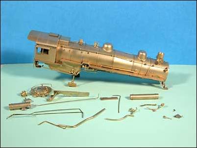
My first step was to strip the paint from the boiler as the locomotive was going to be repainted anyway. I quickly found out that all of the previous modifications to the boiler had been secured with epoxy rather than soldered. Jasco paint remover also dissolves epoxy and as a result all the earlier modifications fell off. I ended up with a boiler and a pile of parts as shown below.
Here are some pictures of the boiler after paint stripping:

At this point I needed to choose a prototype locomotive to model before I could start the repair and detailing process. I decided that I would model number 2467 in the early to mid 1950 time era. Working from a combination of present day and era photographs the next step was to rebuild the locomotive’s detail to represent the prototype.


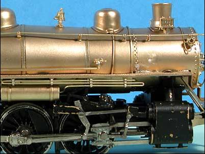
The photo above shows the detail added to the supply side of air pump and the feedwater heater. The lagged steam supply line and air pump governor is routed to match the prototype. The steam supply line for the feedwater pump has been added along with castings to represent the steam strainer and the automatic drain valve. The starter valve and supply lead also had to be reattached as both of these parts had come loose. The present day 2467 no longer has the starter valve, but it was still present in the fifties time era. While not a perfect match the model’s plumbing is fairly representative of the prototype.


This photo shows the air tank and its associated plumbing as compared to the prototype locomotive. Once again the model is a fairly close match to the prototype.


The photos above compare the air piping running back to cab on the engineer’s side of the locomotive. I don’t have any present day shots of engineer’s side of number 2467 so the prototype photo of number 2472 is being used as a stand in. Photographic evidence from the fifties shows that the engineer’s side piping from both locomotives was nearly the same and it closely matches the present day 2472.

These photos compare the plumbing details of the air cooling coil on the Engineer’s side of the locomotive
Page 3 - Last updated August 28, 2005