Rebuilding the driveline
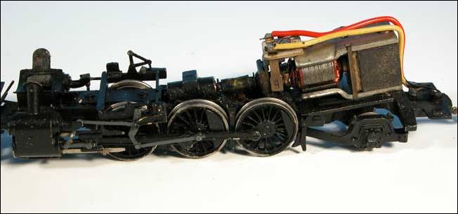
As this model was made in 1965 it contained an old open frame motor that was in need of an upgrade. The usual stiff piece of plastic tubing connected the motor to the original KTM made gearbox. All of these parts will be replaced with new parts from NWSL and a new universal joint coupling will be installed.
But first here is a picture of the driveline in its original form:
For the replacement parts I chose a NWSL 20 x 32 mm motor and a NWSL 28:1 non idler gearbox. Since there is a lot of room in between the frame a larger 0.4 mod gearbox can be accommodated easily. The top corner of the gearbox did however require a little filing to clear the valve gear hanger bracket.
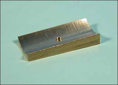
As the new motor is round it requires a mounting cradle to allow it to mount on the locomotive’s frame. A motor cradle was milled from a piece of 3/8” x ½” bar stock using a ¾” (19mm) ball end mill. A hole was drilled and tapped in the bottom to allow the cradle to be mounted using the original motor’s mounting screw. I secured the motor to the cradle using silicon sealant. The motor was positioned so that the mounting holes were facing up.
Here is a picture of the new motor cradle that I made:
If you have read any of my other write-ups you know that I like to use universal joints and an overhead torque arm to connect the motor to the gearbox.
I fabricated a torque arm from some .016” brass sheet stock. The width of the torque arm is approximately .2’’ wide and its length was cut to fit the installation. On the gearbox side I drilled two 1.4mm clearance holes spaced .1” apart. A matching set of holes was drilled and tapped in the top of the gearbox. On the motor end I drilled a .1” hole in the torque arm positioned to line up with the pre-existing tapped hole in the motor. I then made a bushing, a small washer really who’s inside diameter was .081” and whose outside diameter was .097”. The length of the bushing was .020”. This bushing was placed in the .1” hole in the torque arm and then secured to the motor with a 2mm screw. The bushing is designed to allow the torque arm to rotate even when the screw is tightened down. In the past I have used a shouldered screw for this function, but the bushing is much faster to make on the lathe, and allows a standard screw to be used. The motor end of the torque arm must be free to rotate about the mounting point to allow the gearbox to move side to side when the locomotive negotiates curves.
Here are a couple of different views of the rebuilt drive train:
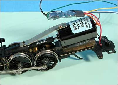
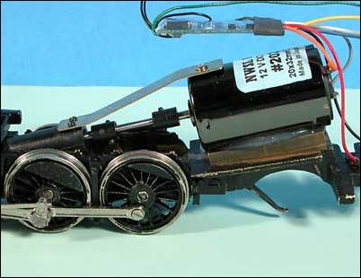
Universal joints from NWSL were used to replace the original plastic tubing coupling. The universals transfer the rotary motion without restricting the natural motion of the gearbox.
Track Testing
At this point I put the locomotive on the track and verified that everything still ran okay with the new drive line. Normally I would go through all the quartering and check everything, but I had already done these steps prior to upgrading the drive line. If you are interested in reading about these steps see my clinic on “Troubleshooting Brass Locomotives” as this locomotive was featured in that clinic.
The new motor and gearbox greatly improved the slow speed starts and eliminated all the gearbox noise that was present in the old gearbox. As you can see from the photos above I also installed a DCC decoder (NCE N14SR) at the same time.
For reference here is a list of parts used in the drive train:
![]() NWSL
20324-9 20mm x 32mm motor
NWSL
20324-9 20mm x 32mm motor
![]() NWSL
241-6 0.4 mod 28:1 gearbox
NWSL
241-6 0.4 mod 28:1 gearbox
![]() NWSL
482-6 U-joints
NWSL
482-6 U-joints
![]() NWSL
21142-5 1.4 x 2mm x 0.3 screws (gearbox end of torque arm)
NWSL
21142-5 1.4 x 2mm x 0.3 screws (gearbox end of torque arm)
![]() NWSL
1203-5 2.0 x 3mm x 0.4 screw (motor end of torque arm)
NWSL
1203-5 2.0 x 3mm x 0.4 screw (motor end of torque arm)
![]() 3/8”
x 1/2" brass bar stock (motor cradle)
3/8”
x 1/2" brass bar stock (motor cradle)
![]() .016”
brass sheet stock (torque arm)
.016”
brass sheet stock (torque arm)
Page 5 - Last updated August 28, 2005